 |
 |
 |
||||||
|
|
|
||||||
The oacAllowedClearanceRange layer pair constraint specifies the range of clearances, in database units, that are allowed between shapes on different layers. A single value can be specified for both the upper and lower bounds of the range, which means that the clearance for this range must be precisely the specified value. Multiple allowed ranges and discrete values can be specified.
| Constraint type: | oaLayerPairConstraint (Symmetric: no) |
| Value types: | oaIntRangeArrayValue, oaIntRangeArray1DTblValue, oaIntRangeArray2DTblValue |
| Database types: | oaTech |
| Object types: | oaAppObject |
The following value types are supported by this constraint:
This oaIntRange value is stored in an array table type object. This value is used when the clearance is independent of width.
Units: DBU
This oaIntRange value is stored in an array table type object. This value is used when the clearance is dependent on the width of one of two shapes.
Units: DBU
This oaIntRange value is stored in an array table type object. This value is used when the clearance is dependent on the width of both shapes
Units: DBU
The following parameters are supported by this constraint:
| Name | Value Type | Units | Default | Description |
|---|---|---|---|---|
| width oacWidthConstraintParamType |
oaIntValue | DBU | None |
This constraint applies when both the width of the shape on layer 1 and the width of the shape on layer 2 are less than the given width value. |
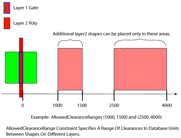
Some process technologies define clearance rules between gates and other polysilicon shapes including dummy poly. The rule usually applies when the cumulative run length between a gate shape and the facing poly shape exceeds a certain value.
Copyright 2002 - 2010 Cadence Design Systems, Inc.
All rights reserved.