 |
 |
 |
||||||
|
|
|
||||||
The built-in layer constraint definition oacMaxDensity specifies a percentage value from 0 to 100 that represents the maximum percentage of an area of the design that must be filled with shapes on a particular layer. Density constraints are generally represented in two ways: the maximum density for an area that encompasses the entire design, or a window-based maximum density where the area of concern is a window that is moved across the design to prevent localized problems.
The built-in layer constraint definition oacMinDensity is used in conjunction with the oacMaxDensity constraint to make sure that the metal density for a design is neither too dense nor too sparse.
| Constraint type: | oaLayerConstraint |
| Value types: | oaFltValue, oaIntFltTblValue |
| Database types: | oaDesign, oaTech |
| Object types: | oaAppObject |
The following value types are supported by this constraint:
This value represents the maximum density percentage required for one layer over the entire design.
Units: Percent
The oaIntFltTblValue where the lookup key ("step") represents the step size and the value represents the density percentage.
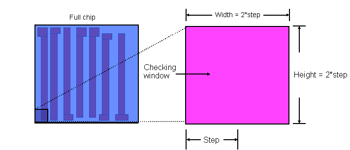
Checking density using a stepped value requires that you start in a corner of the design and validate the percentage for an area (window) whose height and width are each twice the step size. You then continue stepping across the design incrementally, moving your window of concern by the step size, each time validating that the density percentage in the window does not exceed the maximum value required.
Units: Percent
The following parameters are supported by this constraint:
| Name | Value Type | Units | Default | Description |
|---|---|---|---|---|
| windowStepSize oacWindowStepSizeConstraintParamType |
oaInt1DTblValue | DBU | None (only valid for value types: oaIntFltTblValue) |
This parameter holds a table for different window and step sizes. The value corresponding to the step size is considered as the window size in database units |
The primary reason for metal density rules is to eliminate improper etching between geometries. If shapes are too close together, dense spacing does not allow enough room to etch the metal layer between the shapes, and underetching can occur.
Copyright 2002 - 2010 Cadence Design Systems, Inc.
All rights reserved.