 |
 |
 |
||||||
|
|
|
||||||
The built-in layer constraint definition oacMinWireExtension specifies the minimum distance a wire must continue past a via cut. The distance is specified in database units.
Wire extensions are specified from the center of the via cut to the inside edge of the wire shape. The contraint definition applies to both cut layers, the one below and the one above.
| Constraint type: | oaLayerConstraint |
| Value types: | oaIntValue |
| Database types: | oaDesign, oaTech |
| Object types: | oaRoute, oaScalarNet, oaBusNetBit, oaAppObject |
The following value types are supported by this constraint:
This value represents the minimum wire extension in database units.
Units: DBU
The following parameters are supported by this constraint:
| Name | Value Type | Units | Default | Description |
|---|---|---|---|---|
| coincidentAllowed oacCoincidentAllowedParamType |
oaBooleanValue | Boolean | False |
When the coincidentAllowed parameter is specified and is true, then shapes can either meet the minimum extension or their edges can be coincident. If the parameter is false or is not specified, then the edges must meet the minimum extension specified and cannot be coincident. |
| distance oacDistanceConstraintParamType |
oaIntValue | DBU | None |
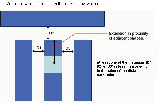
If the distance parameter is specified, the constraint is applied only if there are additional neighboring geometries on layer one (the extended layer) that are located within the value given by the distance parameter to the extension beyond the via cut. |
Extension rules ensure that the necessary overlaps are maintained to provide good connections after manufacturing. These kinds of constraints are common for metal shapes over cuts. If the process shifts the metal layer, the metal might uncover the cut and the resulting connection would not be clean. Providing the minimum extensions of the metal past the cut ensures that with the process variations and differences, the correct connections are maintained.
Copyright 2002 - 2010 Cadence Design Systems, Inc.
All rights reserved.